Introduction
Hello! This resource is meant for anyone with some *nix/software/exploit dev. experience, but with little to no hardware/electronics background! While the ins and outs of basic circuits won't be covered (as there are many great resources for that online), the information is meant to be presented in a way that does not require previous experience.
The main goal of this resource is to help anyone who is trying to do vulnerability research and/or exploit development on a physical device, and who does not have a debugging setup, shell, or firmware! Or, better put: let's get you some root shells without the hassle of finding a 0-day! <3
Recon
Before obtaining a target device, it is useful to do some preliminary inspections. In the US, any devices using RF (Radio Frequency) communication (think WiFi, Bluetooth, etc.) has to be tested and approved by the FCC. These tests are publicly accessible and usually contain internal pictures of the device!
To find these FCC tests, you first need to obtain the device's FCC ID. This ID is always present on the outside of a device, and is usually grouped with other technical information and specifications. For this example device, the FCC ID is at the bottom.

You can search for this ID directly in the FCC's official lookup site or use sites such as fcc.io or fccid.io to automate the process. From there you should be able to see a variety of documents such as user manuals, RF test info, and internal/external device pictures! These pictures can help you identify any possible hardware debug interfaces, interesting components, CPU architecture, etc.
Cracking Open Hardware
Typically, hardware devices are held together via a combination of screws, glue, and (almost always) pressure-fit plastic clips. Plastic clips are the bane of every hardware hacker's existence, but usually come apart with a reasonable amount of pressure from a flat head screwdriver or pry tool. (As an aside, please remember to point sharp edges away from yourself!)
Tip: If a device doesn’t come apart easily, try checking underneath stickers or rubber ‘feet’ on the underside of the device for screws.
When consulting FCC documentation or peeking under the plastic shell of a device, there are several key things to look for:
1. To find out more info about the device
Look for the CPU. It is usually the largest flat black square on the board - reading the label and putting it into your search engine of choice should lead to some datasheets describing architecture, pinouts, and more.
Similarly to the CPU, any larger chip on the PCB (Printed Circuit Board) can give some helpful information about the device (RAM, storage, etc.)
2. To obtain device firmware
See the "Via Hardware" section of the "Obtaining Firmware" section below.
3. For shells
To obtain a shell or interactive debug session on the hardware, keep reading!
Communicating with Hardware
Just as a binary can be compiled with debug symbols, hardware engineers can design their devices with features such as debug headers that provide a way to communicate with components on the PCB. These interfaces are used during development to aid debugging and are often required during device manufacturing to load firmware and/or run automated tests. As such, these headers are usually not removed in the final device and can provide an excellent entrypoint for the curious reverse engineer.

Debug headers (or debug pins) typically consist of a cluster of connections arranged in a standard, easily-recognizable arrangement on the PCB. They may already be soldered to a PCB header (which makes it easy to connect external devices) or you may have to warm up your own soldering iron and attach some new wires.
Note: Debug headers for embedded CPUs are often just direct connections to pins on the CPU itself. If the debug headers are broken or missing, it is possible to ignore the rest of the PCB and directly connect to these CPU pins. Special tools such as the lovely pcbite help with those kinds of small-scale connections.
While there are many hardware communication protocols
(JTAG, I2C, SPI, CAN, …) we will focus specifically on UART in the rest of this blog because it is one of the most common protocols for debug interfaces.
U-What?
Universal Asynchronous Receiver/Transmitter (or UART) is a simple but elegant protocol. As the name suggests, it allows for a device to receive and transmit data, asynchronously. A UART connection typically looks like this:

A UART interface consists of 4 pins:
- GND: low voltage, e.g. 0V
- Vcc: high voltage, commonly between 3.3V and 12V
- Rx (Receive)
- Tx (Transmit)
The Rx and Tx pins are held at the high voltage when idle and oscillate between the low and high voltage when sending information.
Using a fancy circuit analyzer, we can examine a live UART transmission.

Each row shows the voltage over time of an individual UART pin during a live transmission. In this transmission, the device we are measuring is receiving data.
- Channel 0 (GND) remains at a low voltage
- Channel 1 (Vcc) remains at a high voltage
- Channel 2 (Rx) switches between low and high voltage as data is transmitted
- Channel 3 (Tx) is held high (indicating no data transfer)
The data is being transmitted in the form of bits (0’s and 1’s) encoded as pulses of low and high voltages on the Rx pin. The UART protocol describes how bits are packaged into 5-9 bit frames which include special control bits (start/stop) and error correcting bits (parity). However, an important feature to consider is that the receiving device must measure these voltages at the same speed that the transmitting device is sending them. If the receiving device is measuring too quickly or too slowly, the received bits will be incorrect. Therefore, we need to make sure both devices are talking at the same speed. Hence, we need to talk about…
Baud Rates
For a great, in-depth definition of baud, baud rates, bit rates, and more: stackoverflow to the rescue! However, for our purposes the baud rate of a UART device is simply how many bits/sec are being sent over the wire.
Most devices operate with a baud rate of 9600 baud (9600 bits/sec or 1200 bytes/s) or 115200 baud. There are many standard baud rates (usually multiples of 9600) but 9600 and 115200 are almost always the default rate. Tricks for identifying baud rates will be expanded upon later on :)
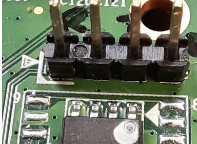
UART Header
With that introduction out of the way, when looking at the inside of a device you can come across something like this:

This unnamed manufacturer was even kind enough to label the pins for us!
Naturally, every engineer across every vendor may implement things differently. There are two main areas to watch out for:
1. Rx and Tx labelling
If the Rx/Tx pins are labelled, it is almost always a 50/50 guess on whether the labeller intended to mean "Rx" as "Hey! You can receive data here" or "This is where the device receives data". (The same is true for the Tx pin).
Note: Rx and Tx operate on the same voltage, so it is generally safe to be wrong here (and swap later if necessary).
2. Vcc pin
It is not always clear what the Vcc pin is intended to be used for. Normally, if the board is already powered (via USB or a power adapter for example), there is no need to interact with the Vcc pin as it will already be connected to the board’s internal Vcc. In fact, incorrectly interacting with this pin by trying to attach a different power supply can short the two power supplies, frying the device and damaging your equipment! (I unfortunately know this from experience.) In short: DO NOT CONNECT THIS PIN
Getting a Root Shell
All of the above info is great (hopefully) but you didn't come here to learn about hardware protocols, you came to get some root shells!
As mentioned above, there is some ambiguity when dealing with UART. Sometimes the Vcc pin is not even included, sometimes the labeling can be wrong, etc. However if you spot three or four pins in a row on a board, you most likely are dealing with UART :)
In the event your board has its debug pins labeled, skip down to the Interfacing section. Otherwise, let's get multi-metering!
Identifying Pins
There are a variety of ways to reverse engineer UART pinouts, ranging from dumb luck to $1000+ hardware. We're going to stick with a lower-tier option: multimeters! If you do not already have one lying around, they can be acquired for as low as $5 if you're resourceful. Nothing fancy is required for UART, any meter that can display voltage in the 0V - 12V range and has a continuity sensing option will work! (such as this or this).
With that sorted:
- Locate the suspected UART pinout. (It may be 2, 3, or 4 pins)
- Power on the target device as normal.
- Set your multimeter to continuity mode. It usually looks like a diode symbol (->+).
- Connect the black probe of the multimeter to a grounded component (usually any exposed metal - stay safe and use housings for ports, "RF shields," etc.)
As seen in the image below, RF shields are the large rectangular metal covers for radio wave emitting components, the shields are almost always grounded.

1. Tap the red probe on each suspected UART pin. If there is a beep (or the multimeter display changes) you found the ground pin! Note: the ground pin is usually a square, but not always.
2. Set the multimeter to DC voltage mode. It usually looks like a “V” with a solid horizontal line over a dashed line. If the meter has fixed voltage ranges, use the closest setting to 12V (round up).
3. Connect the black multimeter probe to the identified ground pin.
4. Tap the red probe to each suspected UART pin. If it reads a stable 3.3V or 5V is it most likely the device’s receive pin. This could also be a Vcc connection, you can check continuity with the powered pin of a barrel jack or usb input connection to verify. If it reads fluctuating values in the 3.3V/5V to 0V range, it is most likely the device's transmit pin. If it reads a stable 0V (or <0.5V), it is likely a ground connection.
The ground connection is the most important. If you are also able to identify Vcc, you can simply take a 50/50 guess on the Rx/Tx pinout and switch them if there is no connection.
Interfacing
Ok! Now that we've identified a potential UART connection, we need a way to actually talk to it. Any USB-to-serial converter should work. However, 4-pin adapters like this or this (better) are the simplest. With these adapters, the pinout is as follows:
Red: Vcc
For our purposes, DO NOT USE THIS CONNECTION!
Black: Ground
Green: (your) Transmit
White: (your) Receive
Connect these wires to the corresponding UART pins on the device as follows:
- Black wire to device ground
- Green wire to device receive
- White wire to device transmit
- Red wire to nothing!

Communicating
We're in the endgame now! Plug in your USB cable, and fire up some software that can handle serial communication:
On Linux-like systems:
1. sudo screen /dev/ttyUSB0 [baudrate]
2. sudo gtkterm -p /dev/ttyUSB0 -s [baudrate]
3. minicom/miniterm are great dedicated CLI tools for this as well
On Windows systems you can use PuTTY for serial communication.
As mentioned earlier, it is important to match the baud rate of the target device in order to properly communicate with it. Since devices usually use a standard rate, we can use a script such as baudrate.py to cycle through and test all of them.
Troubleshooting
I'm not getting any output!
1. Ensure you are running your serial communication tools as root/admin.
2. Double check pinouts (try swapping Rx and Tx).
3. Make sure the device was powered on as originally intended by the manufacturer (i.e. not with the red serial wire).
The output is a garbled mess of broken symbols and unicode.
Your baud rate is most likely incorrect. Try running through the baudrate.py script and see if any other rates show the info you're looking for.
The device won't boot!
This may be a quirk with the usb-to-serial cable. I've seen before that a cable may be sending 1V on it's transmit line as soon as it is powered, which causes some devices to stop booting. Simply disconnect the cable, reboot the device, wait a second, and reconnect your cable
Now what?
After successfully connecting over UART you will most likely come across the boot log of the device, spitting out torrents of debug information. If you are lucky, simply waiting a few moments before hitting the [ENTER] key may present you with an interactive shell running as root :)
Otherwise, you may need to employ a few tricks:
1. At the beginning of the boot process, if you see a prompt asking for input or a certain keypress, push it!
- You may be dumped into an interactive shell for the device's bootloader. While the OS hasn't been loaded yet, you can inspect nvram contents, dump firmware, arbitrarily write to memory regions, and force a boot to a shell by modifying init arguments (see this post)
2. If the bootloader prompt is not present or set to a duration of zero seconds, there are a few possible options:
- Spam CTRL+C at boot. It's a weird trick, but has worked in a few situations.
- If the device utilizes the U-Boot bootloader, it is possible to glitch the hardware to dump you into the interactive bootloader shell. By default, if U-Boot is not able to properly read the firmware image from the flash storage into RAM it will panic and set itself to the interactive recovery shell. To induce this panic (sorry U-Boot), ground an I/O data line of the flash chip momentarily during boot. Manufacturer datasheets are your best friend here!
Obtaining Firmware
Now that you have a root shell, you probably want to do some hacking, in which case a copy of the device firmware will be handy. Obtaining the firmware is beyond the scope of this blog post but here are a few pointers:
1. Download directly from the manufacturer (easiest method):
Some OEMs (Official Equipment Manufacturer) provide compressed firmware images from their websites (meant for manual updates). Try searching for “[device name]” “firmware” if you can’t immediately find the download page. For example: Netgear's download center
2. Network interception
Unfortunately for device security (but fortunately for us!), many consumer devices communicate to OEM endpoints over HTTP. Due to the lack of SSL/TLS, it is sometimes possible to intercept the target device's network traffic during a firmware update to obtain the files. There is also potential to provide malicious firmware updates (See this blog post by ZDI).
3. Via Hardware (Yay!):
Serial: Many great tools and guides exist for automating this process, such as this. Within a device's bootloader, you are typically able to read out contents of flash memory, which contain the firmware image! (as it has not been copied into RAM yet)
Flash dumping: There are many dedicated guides available such as this. With some dedicated hardware tools (such as a TL866II+), you can physically connect to (via desoldering or special clips) on-board flash chips and read out the contents.